Step by step
Universal valve, X-rings and perforated pipe
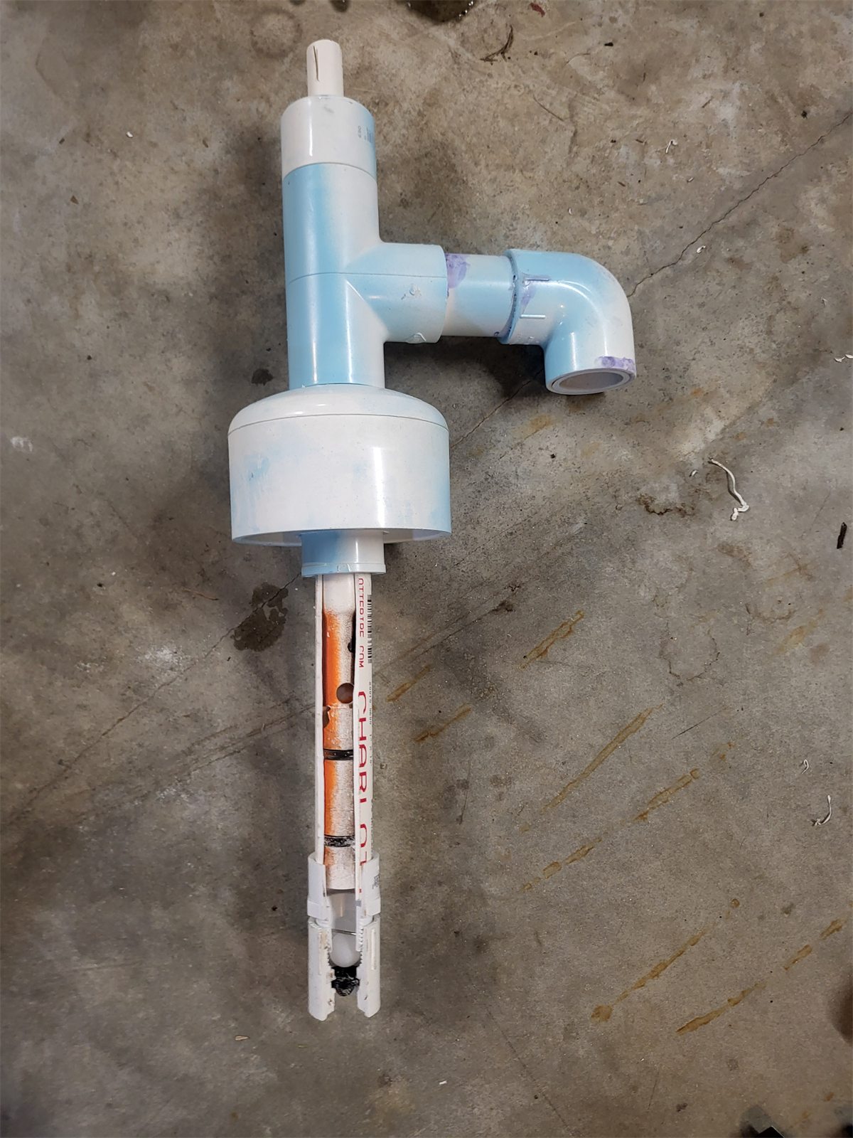
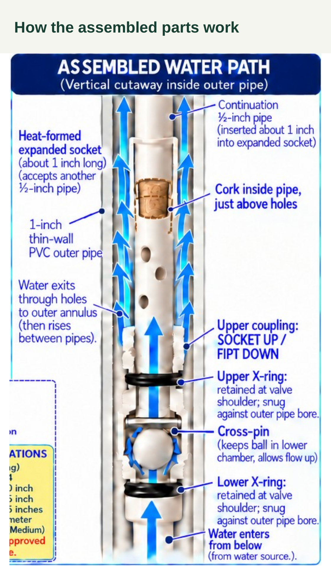
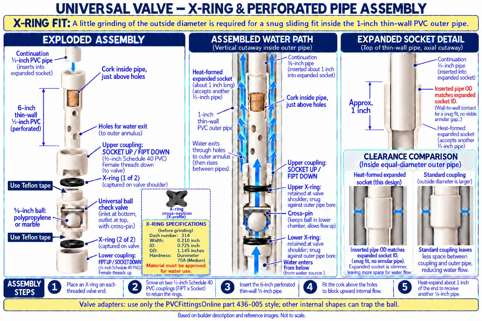
The moving inner valve sends water through side holes and into the space between the two pump pipes.
How the moving inner valve diverts water through side holes into the space between the pipes.
Step 1
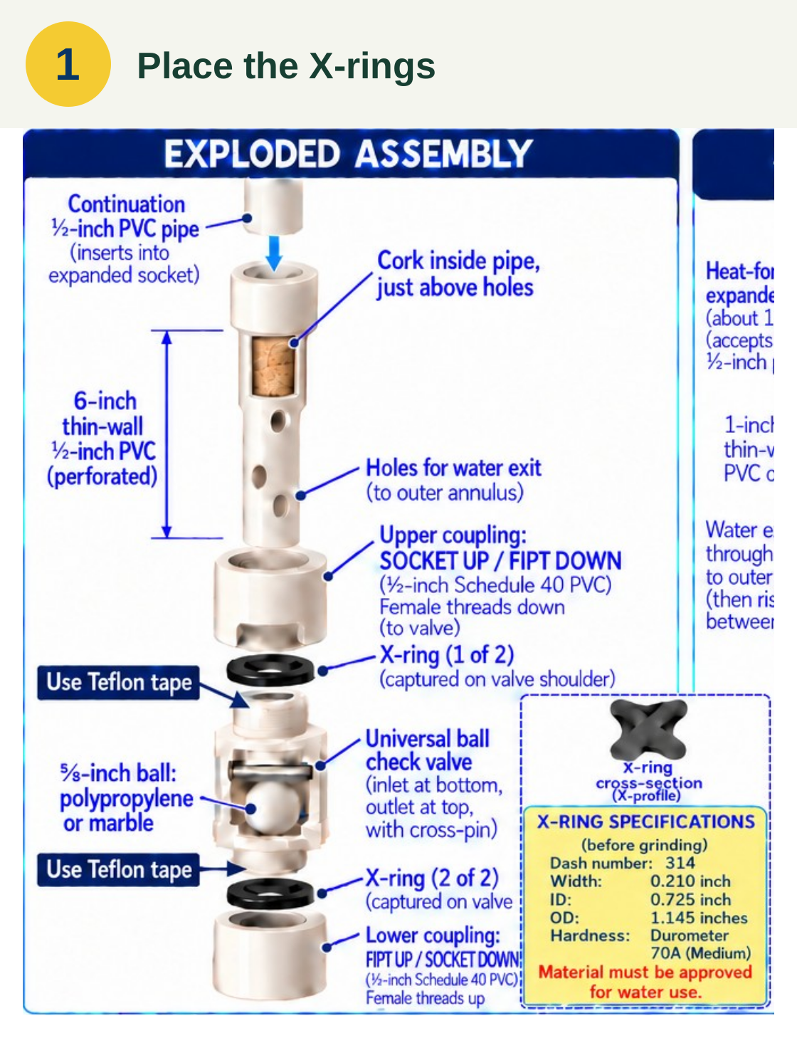
Place the X-rings
One X-ring sits on each threaded end of the moving valve, against its shoulder. These rings seal against the inside of the 1-inch pipe while the valve slides up and down. PTFE thread tape seals both threaded connections.
Place one X-ring on each threaded valve end, captured at the valve shoulder. Use PTFE thread tape on both threaded connections.
Step 2
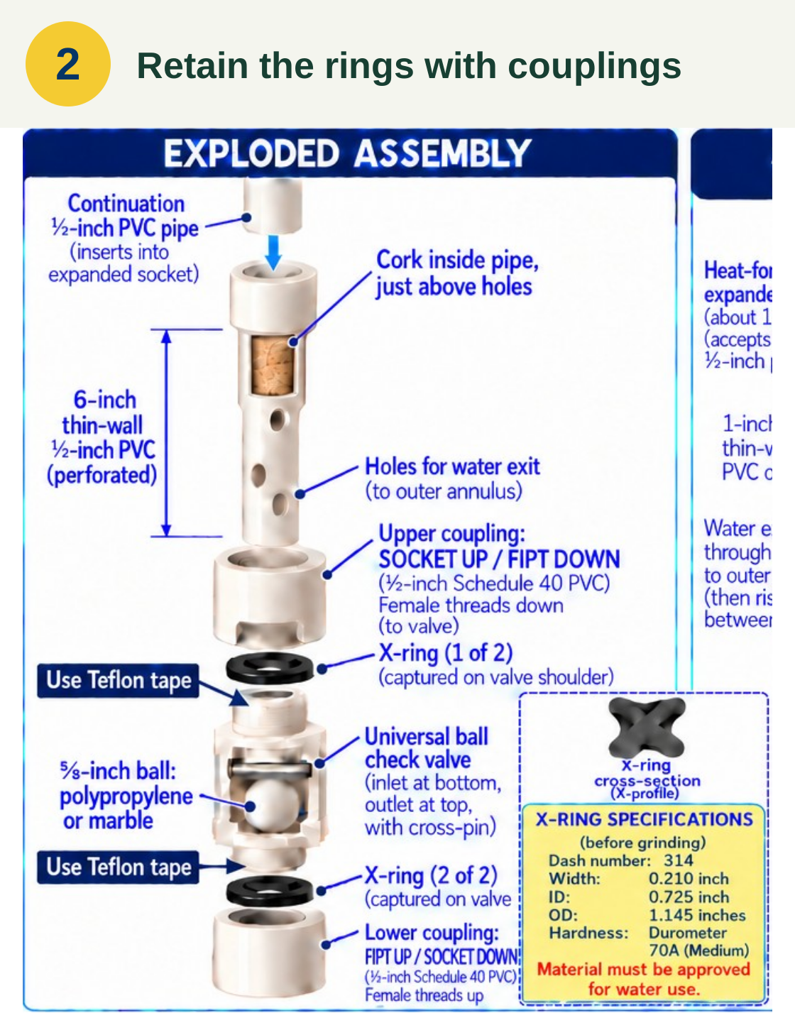
Retain the rings with couplings
Two ½-inch Schedule 40 FIPT × Socket couplings hold the X-rings in place. The upper coupling has its socket facing up and its female threads facing the valve; the lower one has its threads up and its socket down. Together, they retain the rings at the valve shoulders.
Screw on two ½-inch Schedule 40 PVC FIPT × Socket couplings. Upper coupling: socket up, female threads down toward the valve. Lower coupling: female threads up, socket down.
Step 3
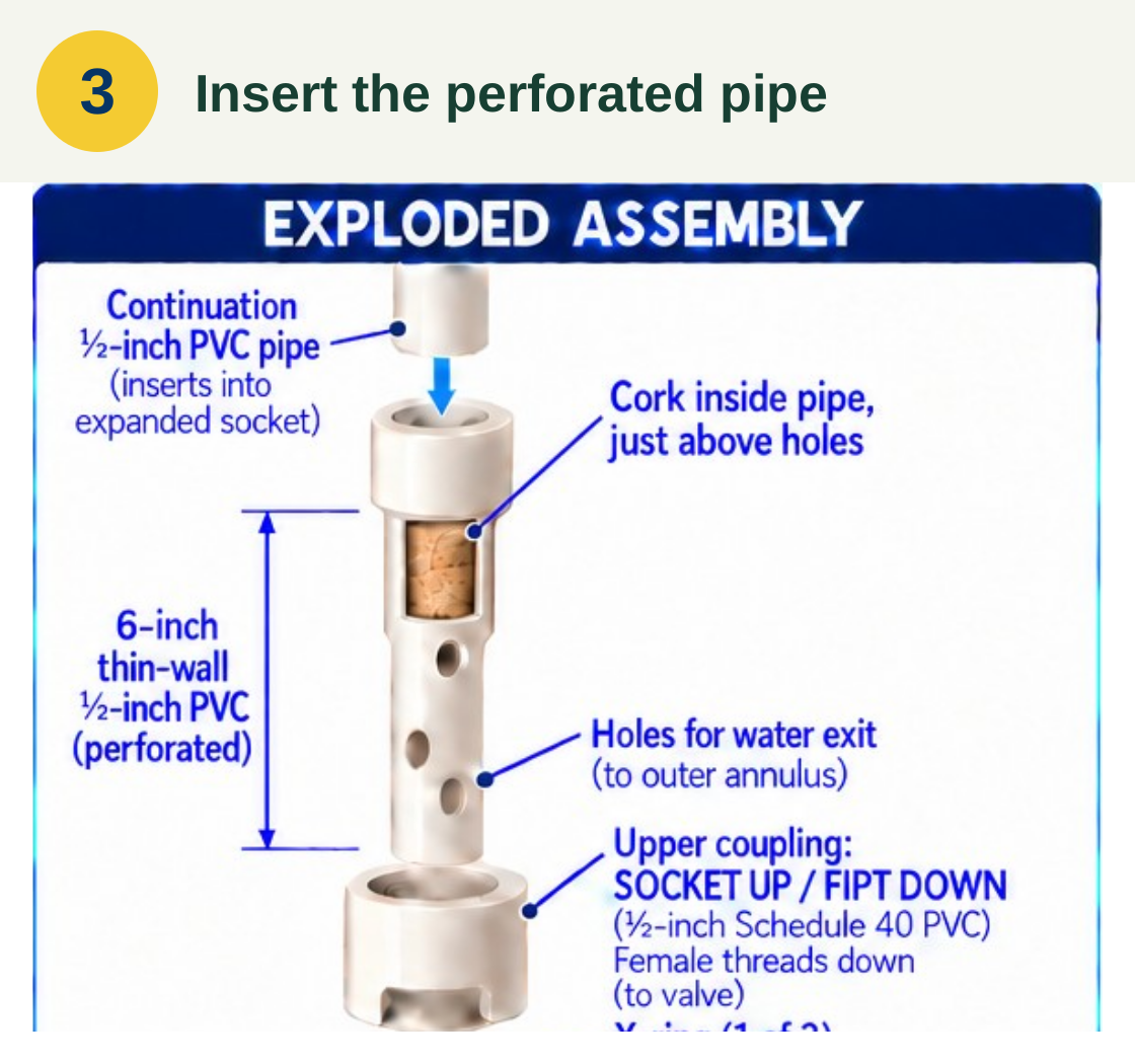
Insert the perforated pipe
Above the valve is a 6-inch piece of thin-wall ½-inch PVC with holes in its sides. Water comes up through the valve and leaves through these holes. From there, it continues upward between the inner and outer pipes toward the spigot.
Insert a 6-inch piece of thin-wall ½-inch PVC with side holes above the valve. Water passes upward through the check valve, exits through these holes, and continues up the annular space between the ½-inch and 1-inch pipes.
Step 4
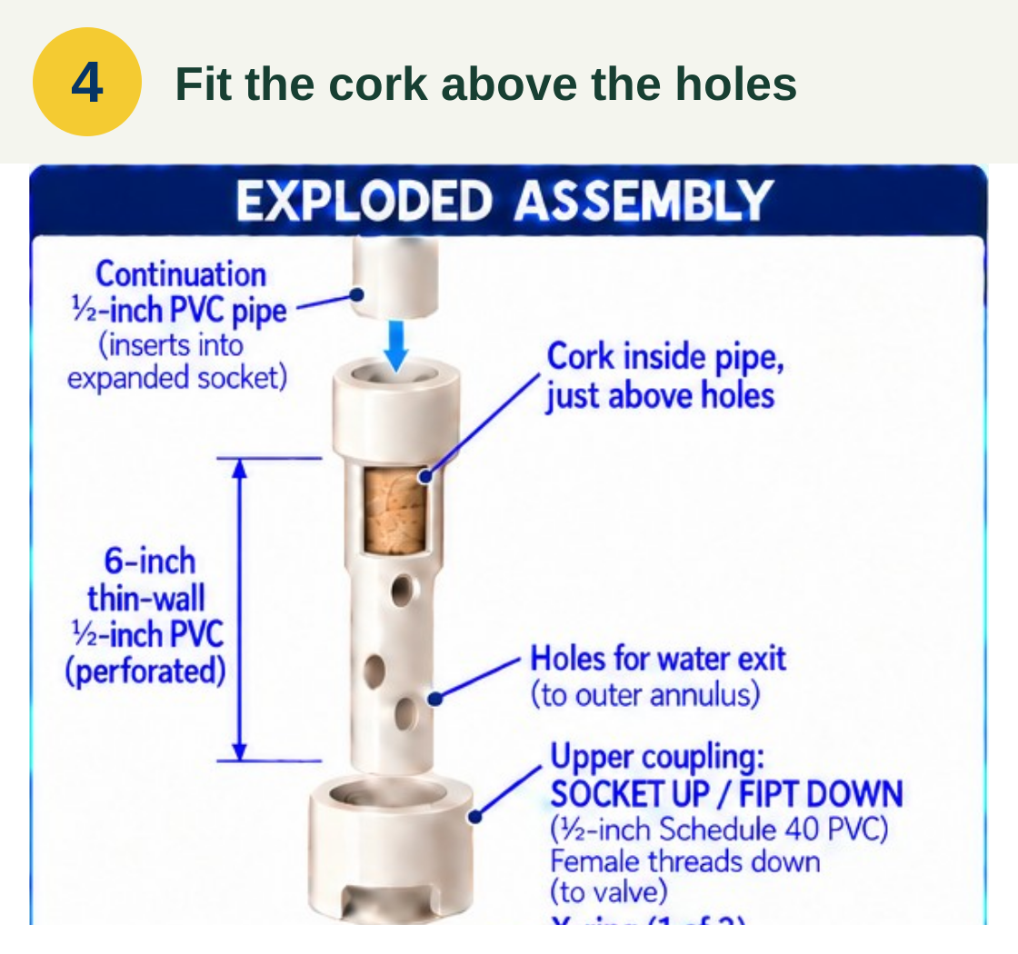
Fit the cork above the holes
A cork sits inside the ½-inch pipe just above the highest hole. It blocks the path farther up the inside of that pipe, directing the water sideways through the holes instead. The water then rises around the outside of the moving pipe.
Fit a cork inside the ½-inch pipe just above the highest hole. It blocks water from continuing up the inside of the moving pipe.
Step 5
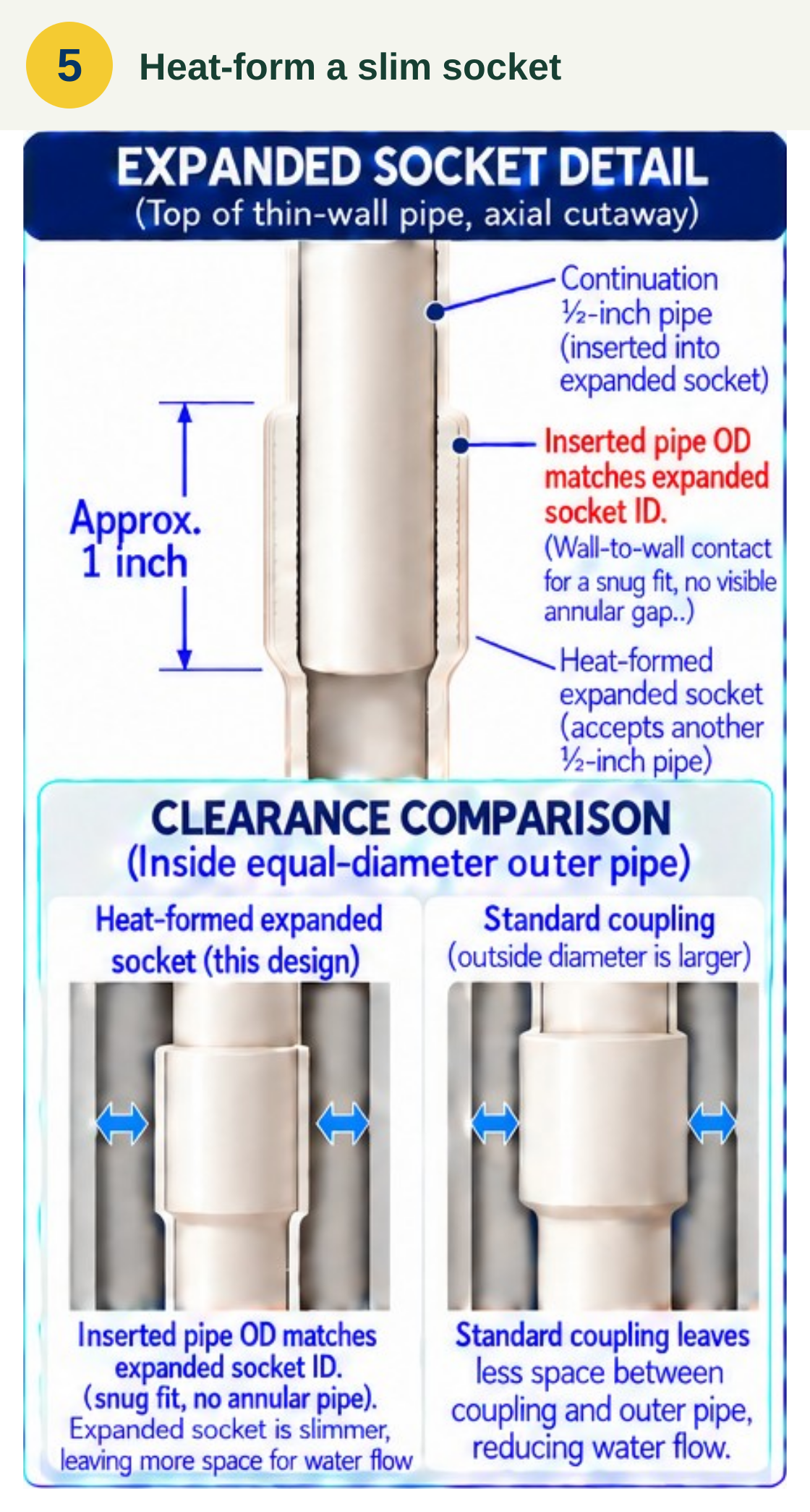
Heat-form a slim socket
We heat-form about 1 inch of the pipe end into a receiving socket for the next ½-inch pipe. The fit is snug, with the inserted pipe’s outside wall meeting the expanded socket’s inside wall. This joint has less bulk than a standard coupling, leaving more room for water to pass between the pump pipes.
Expand about 1 inch of the pipe end to receive the next ½-inch pipe. The inserted pipe’s outside diameter matches the expanded socket’s inside diameter, with a snug wall-to-wall fit and no visible annular gap. This slimmer joint leaves more space for water than a standard coupling.
Preview the complete print sheet
 See the illustrated steps
Construction details
Understand the three nested pipes
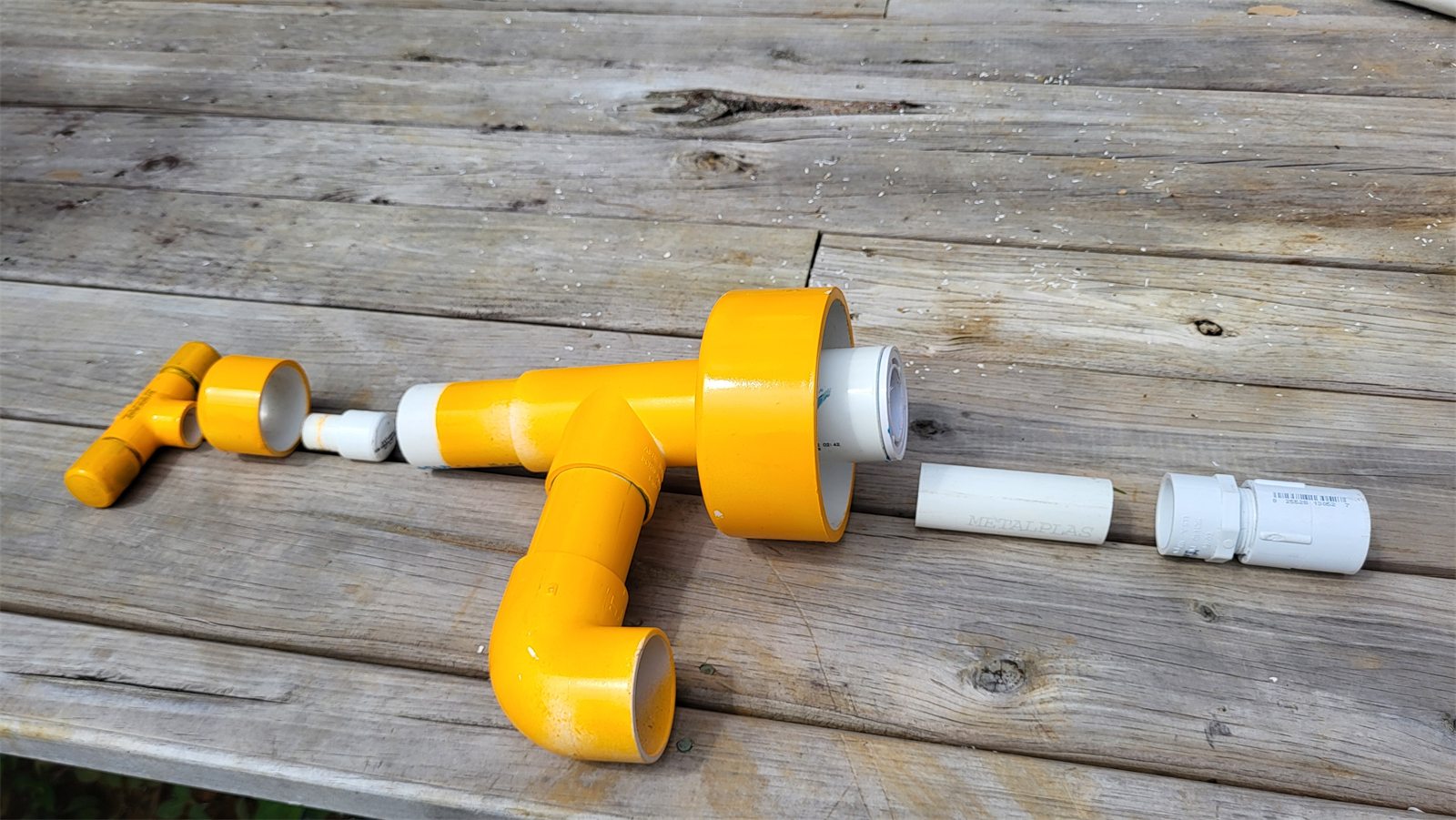
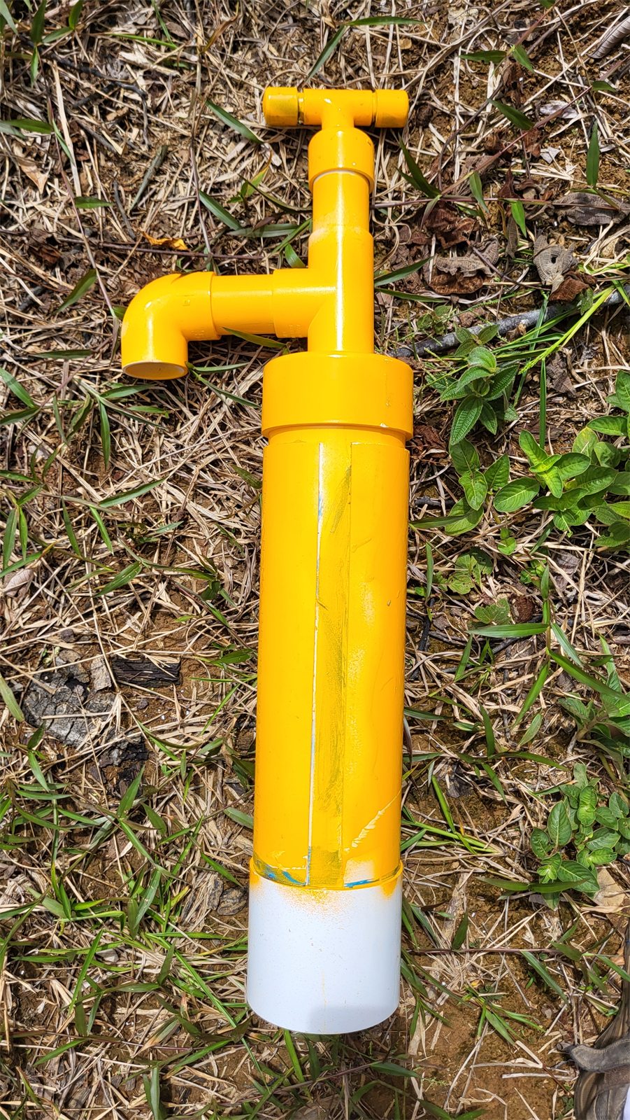
The 4-inch casing lines the well. Inside it, a stationary 1-inch thin-wall PVC pump pipe carries water upward around the moving ½-inch inner pipe. A fixed foot valve sits at the bottom of the outer pump pipe; a second valve moves with the inner pipe. This arrangement does the work without an electric motor.
Set the fixed outer valve 18 inches up
The fixed valve connects to the 1-inch pipe through a reducer. Simón and the family lower this assembly until it touches the well bottom, then raise it 18 inches to keep the intake above settled sediment. That position sets the pipe’s final connection to the reducer beneath the spigot cap, with the fittings and raised wellhead included in the measurement.
Set the inner length by full-down clearance
The moving inner assembly is lowered until it bottoms out, giving a reference for its length. The pipe is then shortened by a few inches before the handle is fitted. With the handle all the way down, the inner valve still sits a few inches above the fixed valve. Checking the full movement prevents the valves from striking each other during use.
Keep the inner water path open
Two black X-rings seal the moving valve against the 1-inch pipe while letting it slide. Water passes through the valve and out through holes in the short ½-inch stem above it. A cork just above the highest hole directs the water sideways, and a slim expanded socket joins the next length of pipe while leaving room for water to rise around it.
Preserve access at the spigot and handle
The spigot head sits above the raised 4-inch riser. Its 1½-inch upper guide cap stays unglued so the inner pipe and valve can be pulled out for service. The T handle attaches to a 5-foot length of ½-inch Schedule 40 pipe, which stands up better to repeated handling. The spigot has a snug rotating fit, while the parts needed for service remain removable.
Inspect and test before normal use
The final checks cover valve direction, seal fit, leaks, and the handle’s full stroke. When sediment-laden water is being pumped out, a sacrificial temporary plunger cap protects the working inner valve. Once the well is clean, the inner pipe is withdrawn and the real foot valve is installed through the removable guide cap. Boiling disinfects the water intended for drinking.