Step by step
Creating the universal foot valve
We make the same small valve in batches for the pump’s inner and outer pipes and for the bailing buckets.
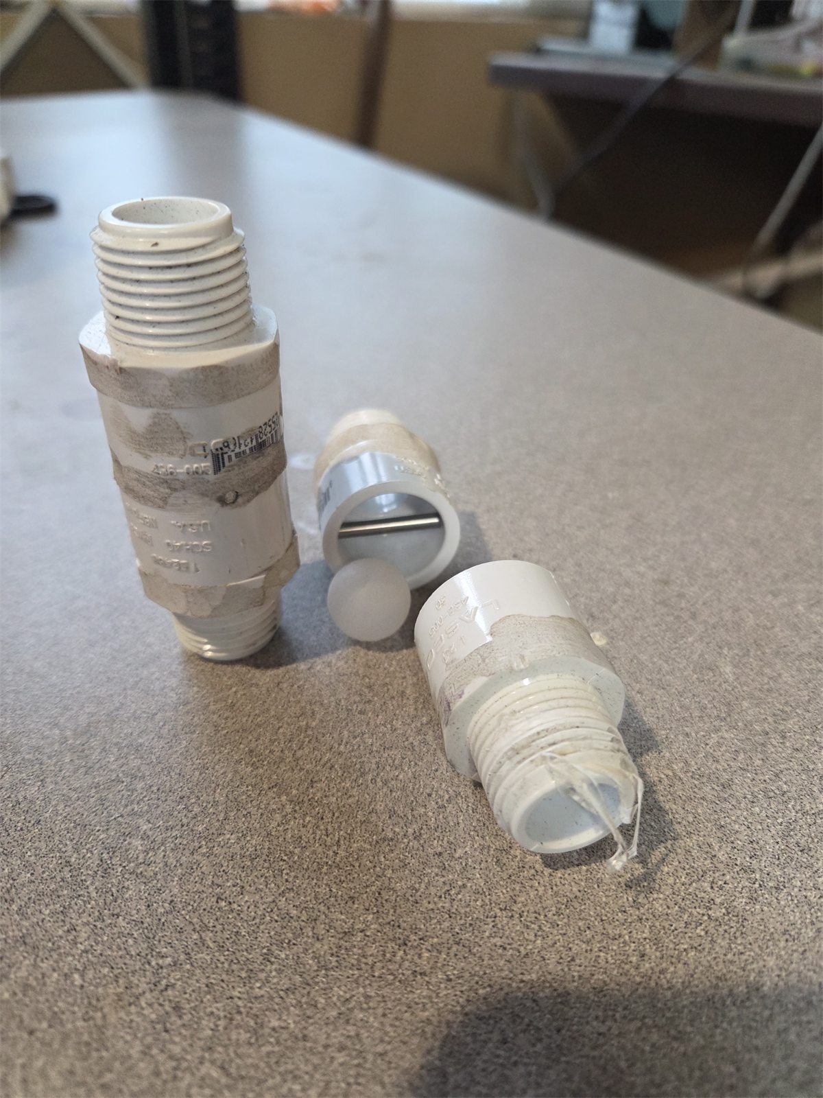
Two PVC male adapters enclose a moving ball and a retaining cross-pin.
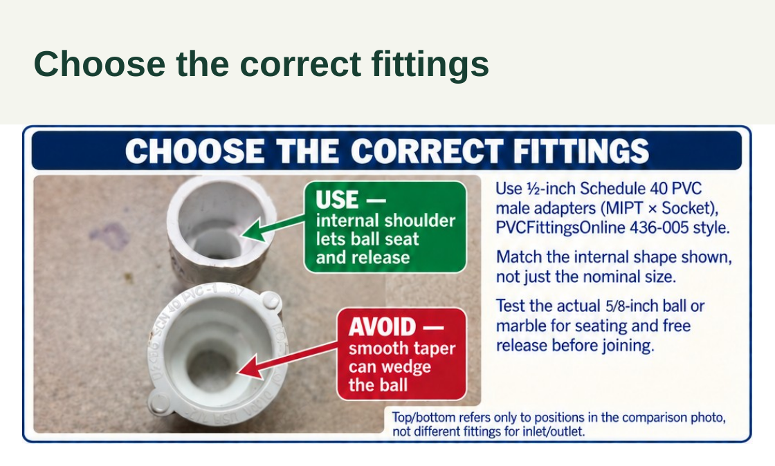
Choose the correct fittings
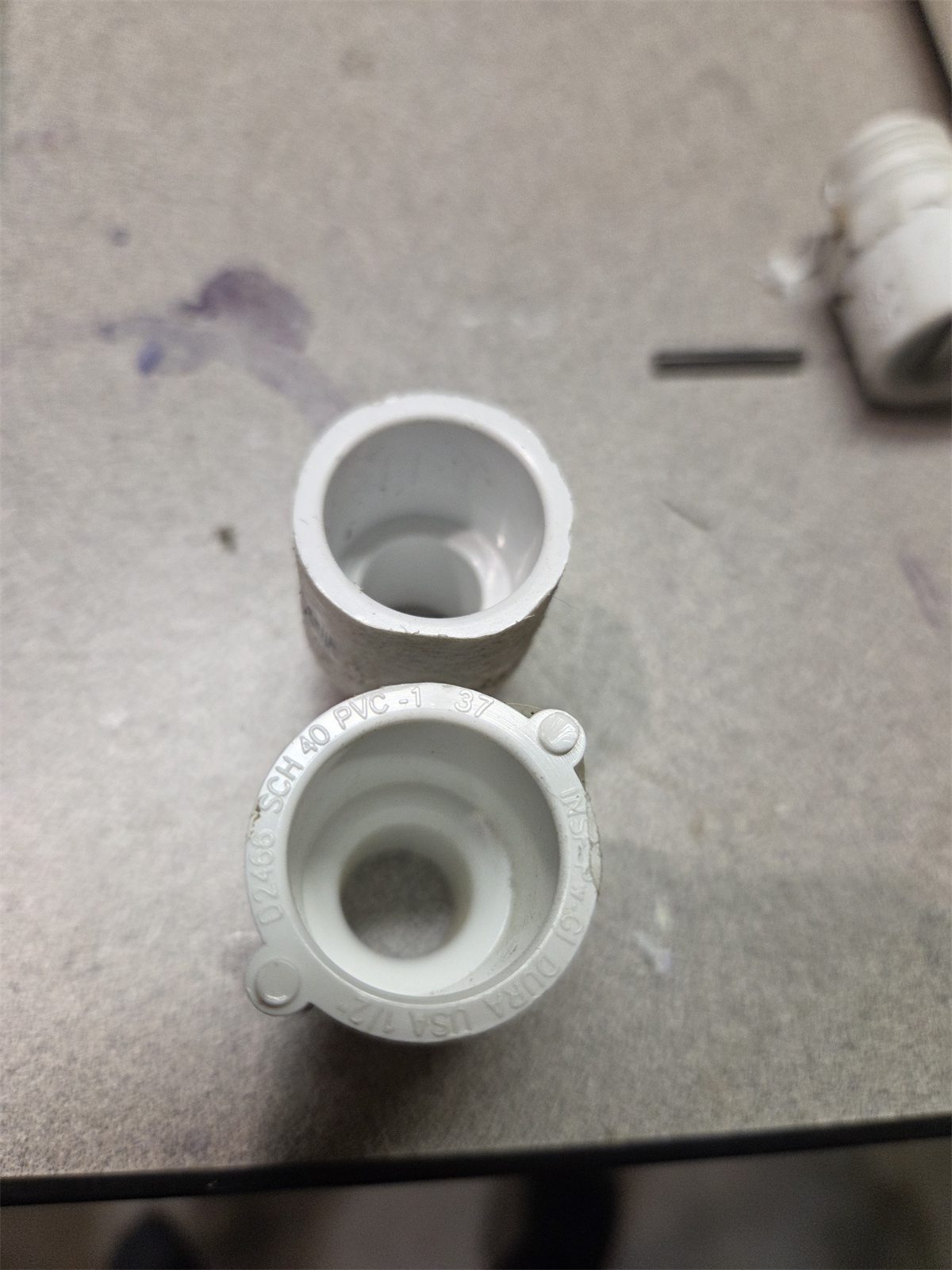
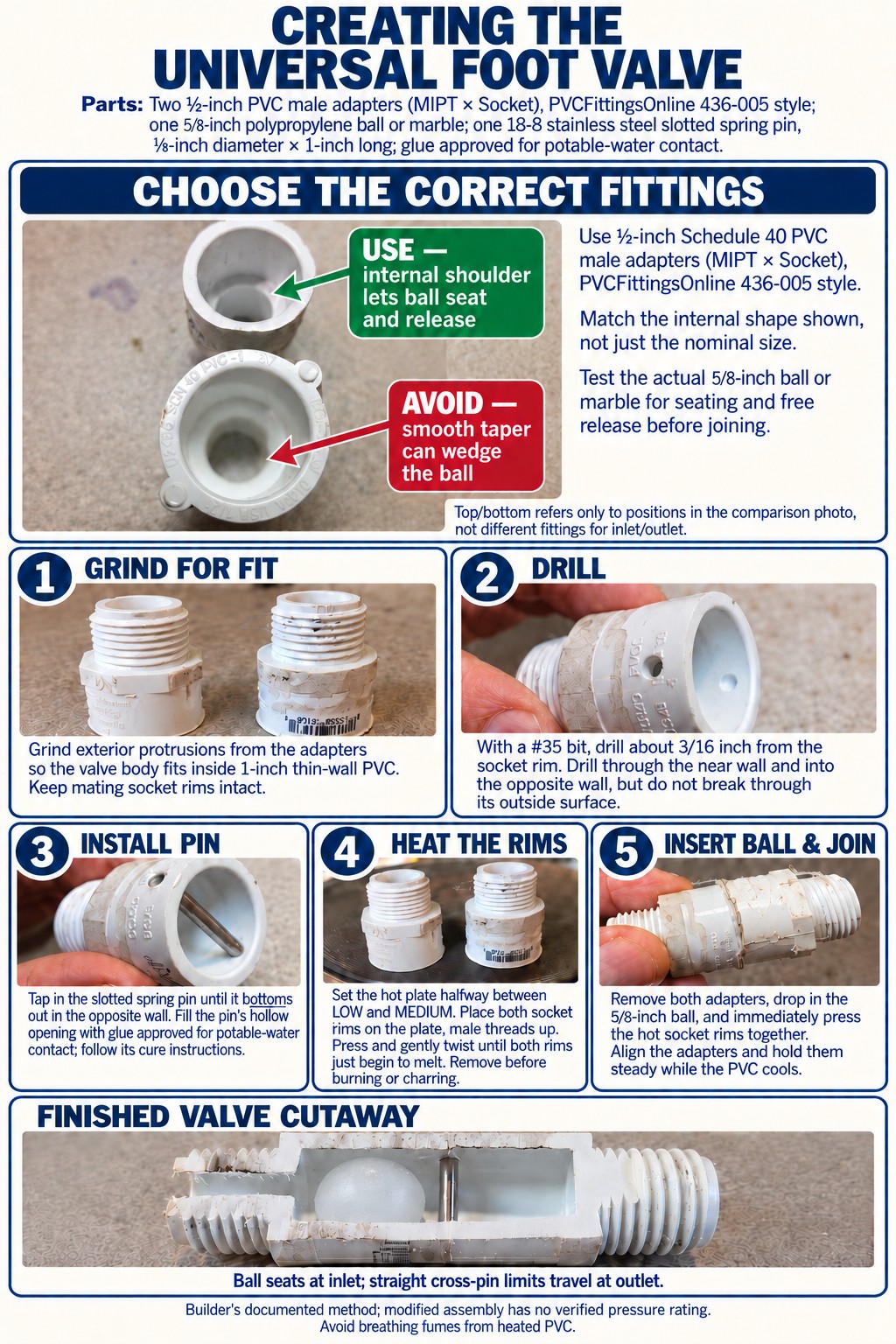
We use ½-inch Schedule 40 PVC male adapters, MIPT × Socket, with the internal shoulder found in PVCFittingsOnline part 436-005. That shape lets the ⅝-inch polypropylene ball or marble seat and release. Other fittings with a smooth taper can trap it, even when their nominal size is the same, so the fit is checked with the actual ball before the adapters are joined.
Use ½-inch Schedule 40 PVC male adapters, MIPT × Socket, with the PVCFittingsOnline 436-005 internal shoulder style. A smooth taper can trap the ball. Test your actual ⅝-inch polypropylene ball or marble for seating and free release before joining.
Step 1
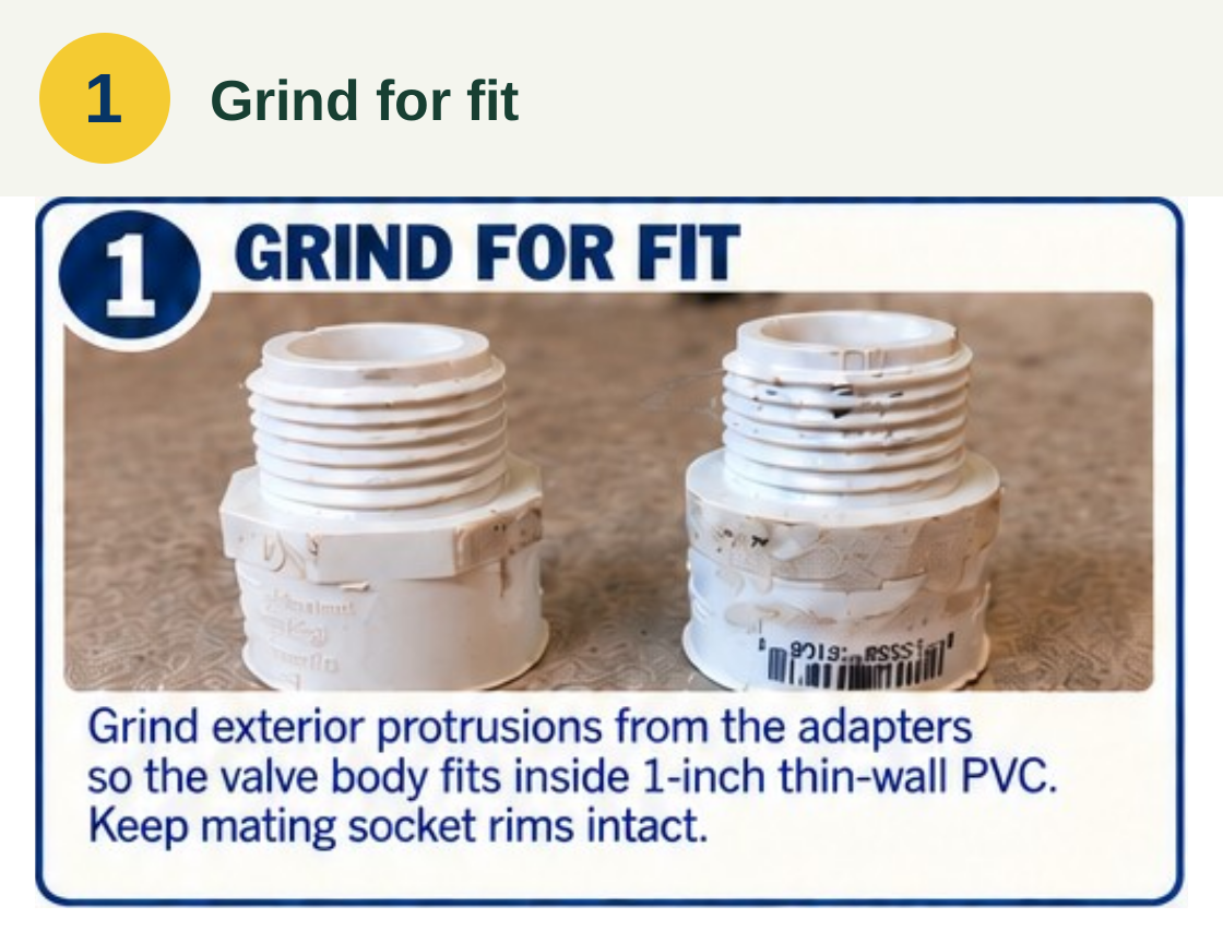
Grind for fit
We grind the raised exterior features off both adapters so the finished valve body fits inside the 1-inch thin-wall pipe. The socket rims and the ball’s seating surface stay intact. Trying the parts in a piece of the actual outer pipe helps us check the fit before joining them.
Grind the exterior protrusions from both adapters until the valve body fits inside the 1-inch thin-wall PVC. Keep the mating socket rims intact and avoid changing the ball’s internal seating surface. Test the fit in a sample of the actual outer pipe before joining.
Step 2
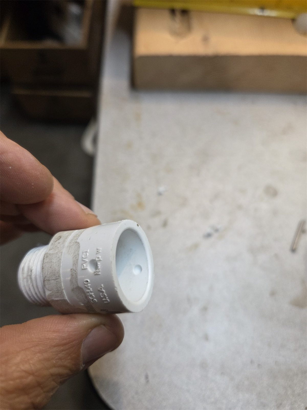
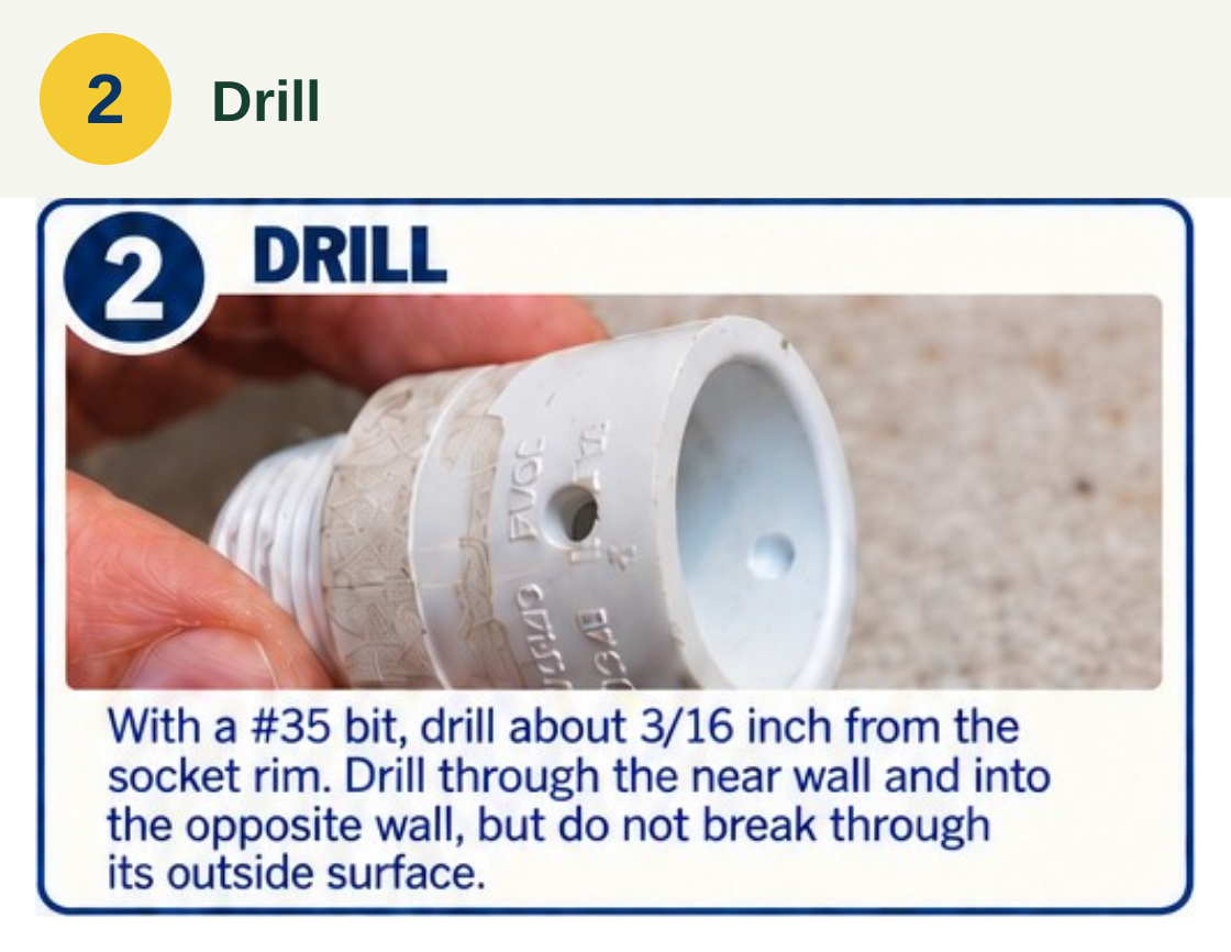
Drill
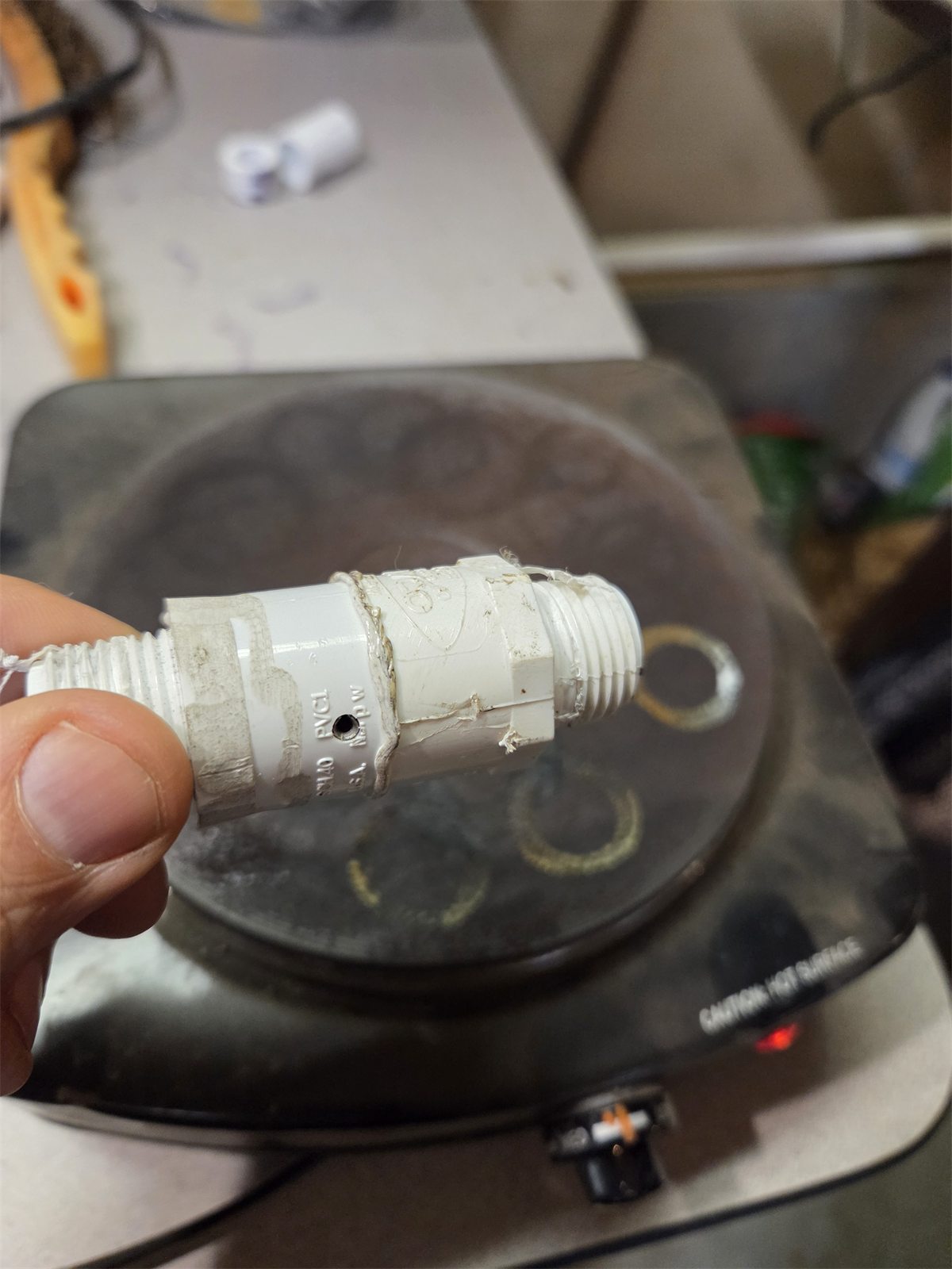
A #35 drill makes the pin hole about 3/16 inch from the outlet adapter’s socket rim. It passes through the near wall and enters the opposite wall without breaking through the outside. This blind end gives the retaining pin a firm stopping point.
Use a #35 bit to drill about 3/16 inch from the outlet adapter’s socket rim. Drill through the near wall and into the opposite wall, stopping before the bit breaks through its outside surface. The blind end supports the retaining pin.
Step 3
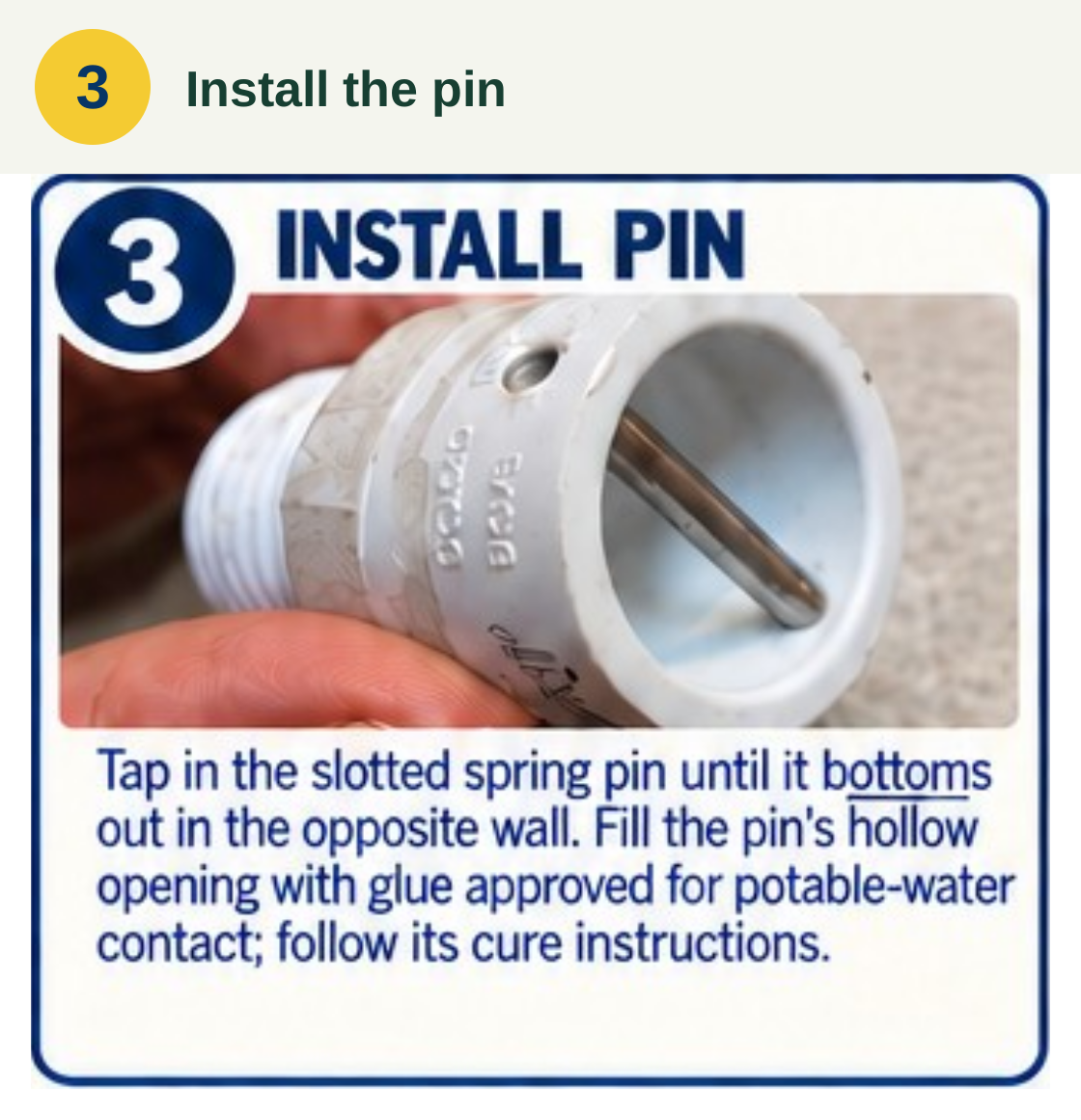
Install the pin
The stainless-steel slotted spring pin is tapped in until it reaches the blind stop. Its hollow opening is filled with adhesive approved for potable-water contact, with curing time allowed according to the adhesive’s instructions. Inside the valve, the pin keeps the ball from rising far enough to block the outlet.
Tap in the slotted spring pin until it bottoms out in the opposite wall. Fill its hollow opening with adhesive approved for potable-water contact and follow the adhesive’s curing instructions.
Step 4
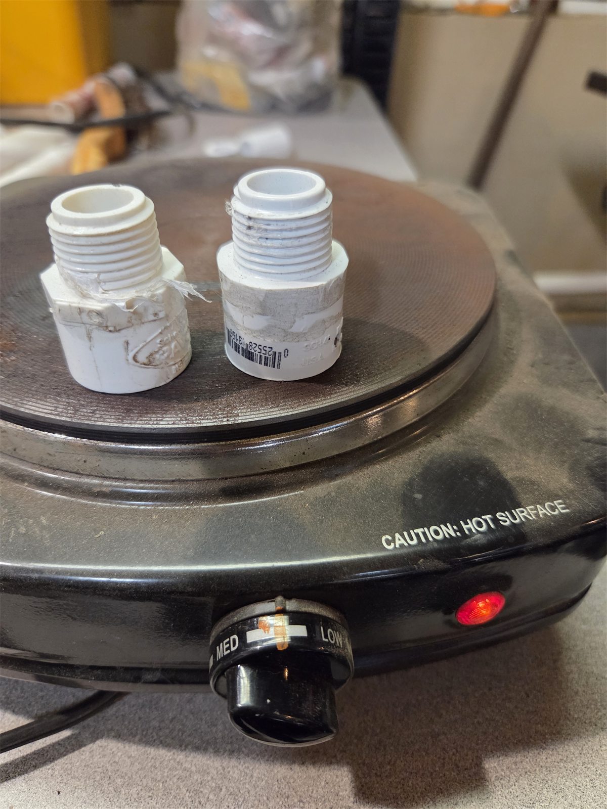
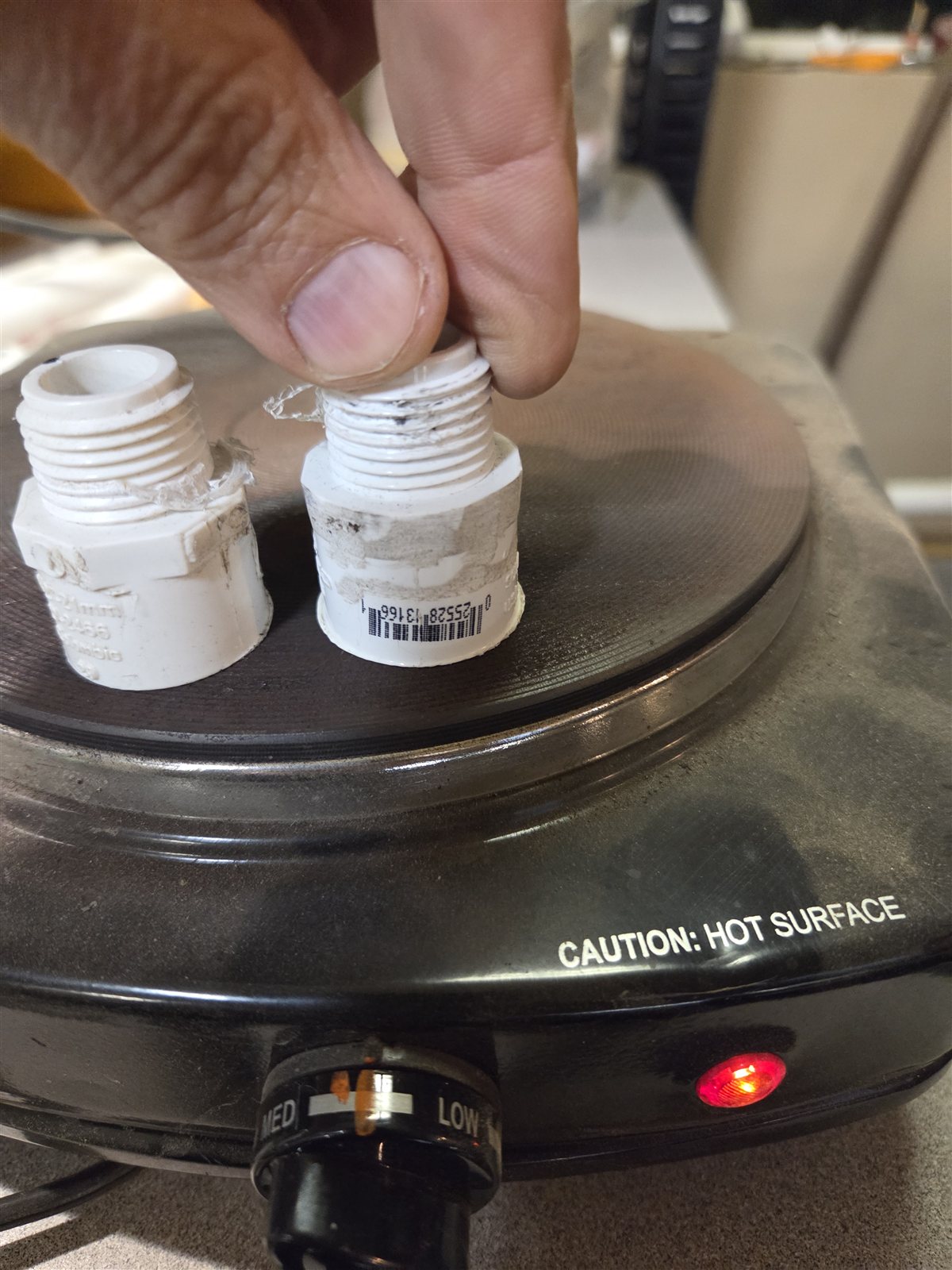
Heat the rims
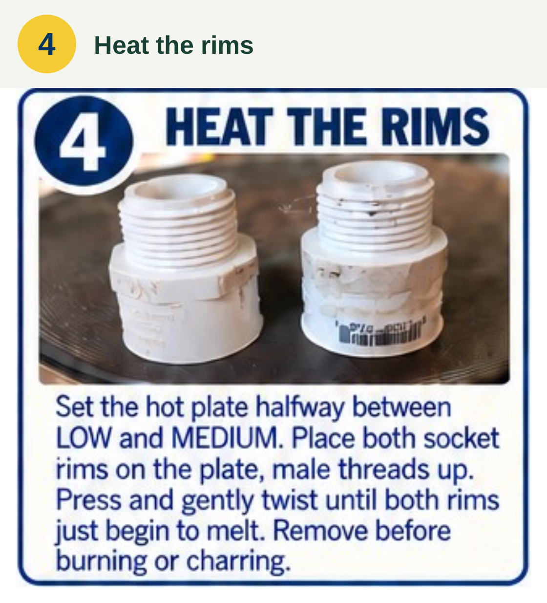
Both socket rims rest on the hot plate with the male threads facing up. We use a setting halfway between low and medium, pressing and gently twisting until the rims just begin to melt. The condition of the PVC matters more than the dial setting: the parts come off before burning or charring.
Set the hot plate halfway between low and medium. Put both socket rims on the plate with male threads up. Press and gently twist until both rims just begin to melt. Remove before burning or charring.
Step 5
Insert the ball and join
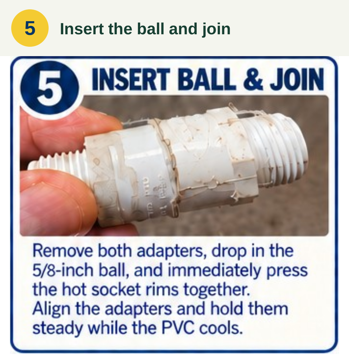
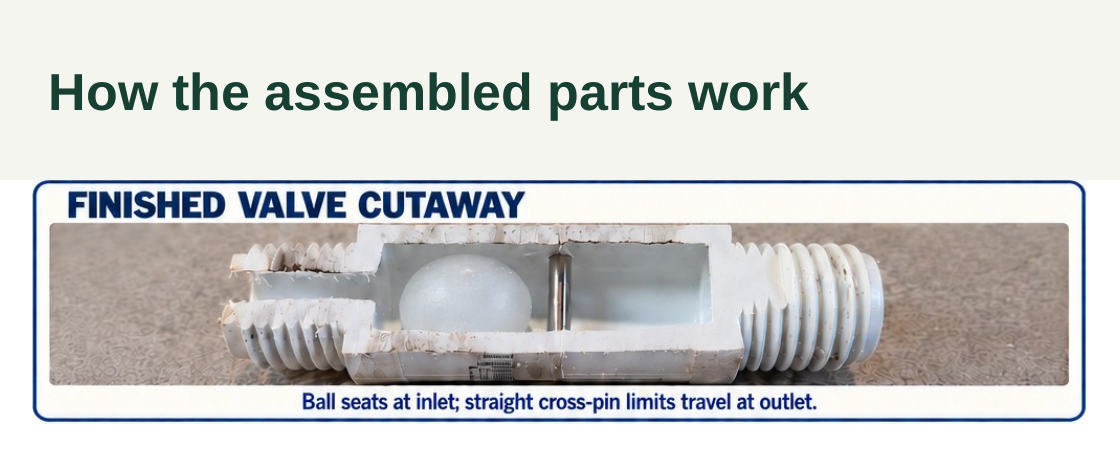
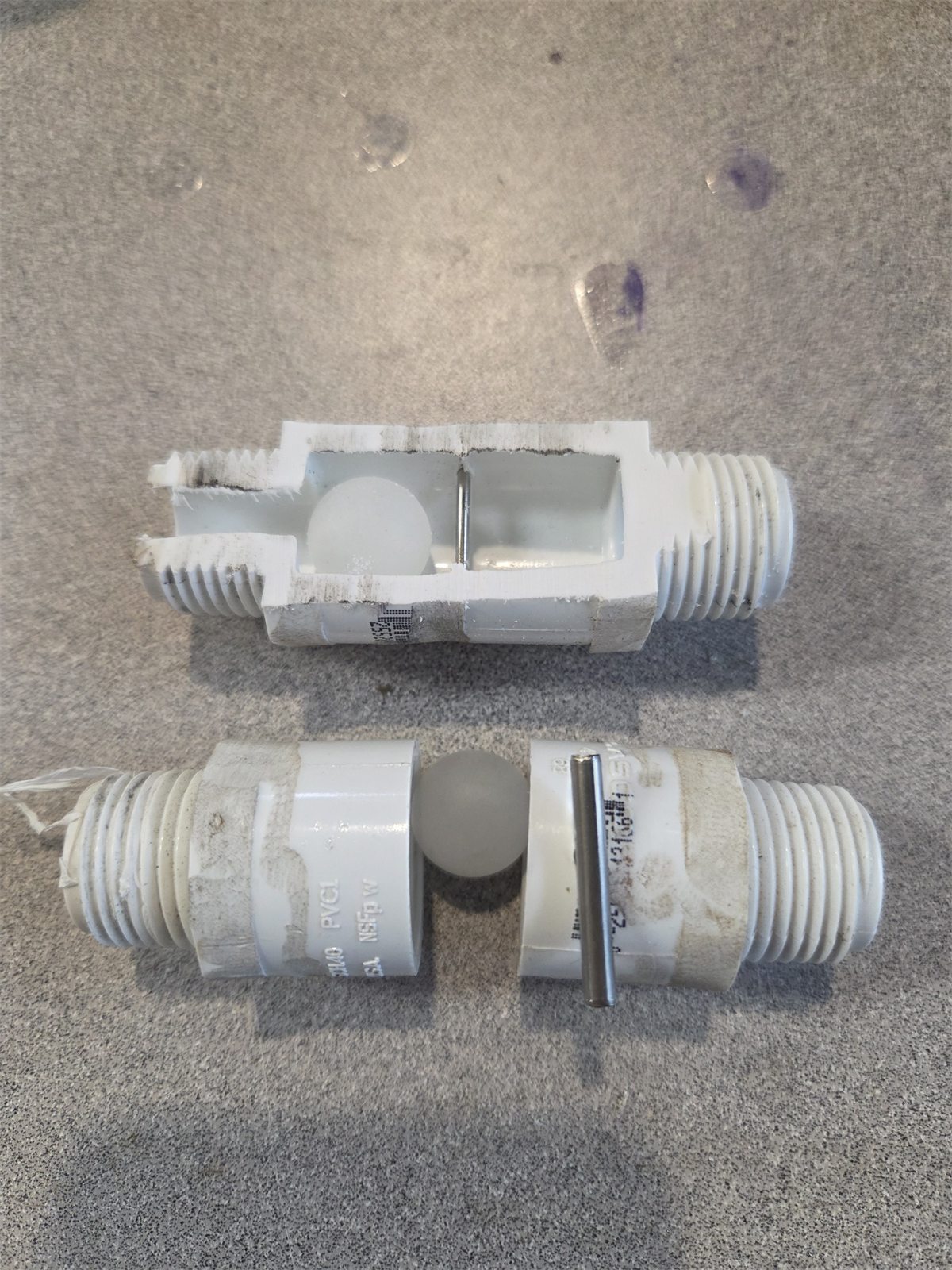
With the adapters off the plate, we drop in the ⅝-inch ball and press the hot rims together. The parts are aligned and held steady while the PVC cools. A finished valve lets the ball seal at the inlet and release freely, while the cross-pin keeps the outlet open. These movement and flow checks are part of preparing each valve for the kit.
Remove both adapters from the plate. Drop in the ⅝-inch ball, immediately press the hot socket rims together, and align the adapters before the PVC cools. Hold them steady until the joint sets. After cooling, check that the ball seats at the inlet, releases freely, and cannot block the outlet past the cross-pin.
Preview the complete print sheet
 See the illustrated steps
Construction details
Identify the components
Each valve encloses a freely moving ball in the chamber formed by two adapters. Their male-threaded ends face outward for connection. The internal shape matters as much as the nominal pipe size: the ball needs to seal and then release without getting stuck.
- Two 1/2-inch Schedule 40 PVC male adapters, MIPT × Socket.
- One 5/8-inch solid polypropylene ball or marble, as specified by the builder.
- One 18-8 stainless-steel slotted spring pin, 1/8 inch in diameter and 1 inch long.
Match the internal seat geometry
We use ½-inch Schedule 40 PVC male adapters, MIPT × Socket, with the internal shoulder style of PVCFittingsOnline part 436-005. That shoulder gives the ⅝-inch ball a seat it can release from. A smooth taper in another fitting can wedge the ball, so we check the actual ball or marble for sealing and free movement before joining the adapters.
Fit the pin as a ball stop
A straight cross-pin inside the outlet adapter limits how far the ball can travel, keeping it from blocking the outlet. Its #35 hole is about 3/16 inch from the socket rim and stops inside the opposite wall rather than passing all the way through. The pin rests in that blind stop; it does not push the ball against its seat.
Join the prepared socket rims
The two socket rims soften on a hot plate with their threaded ends facing upward. We remove them before the PVC burns, drop in the ball, and press the aligned rims together while they cool. Watching the condition of the PVC is more useful than relying on the dial alone. The work also calls for keeping clear of fumes from heated PVC.
Use the shared valve in each assembly
The same universal valve connects to the 1-inch outer pump pipe through a reducer and travels on the moving inner pipe with X-ring seals. Two more go inside the bailing bucket. Some kits still include the legacy 1-inch valve as the outer-valve option. Sharing one small design across these jobs makes batches of kits and replacement parts easier to prepare.
Check movement, flow, and materials
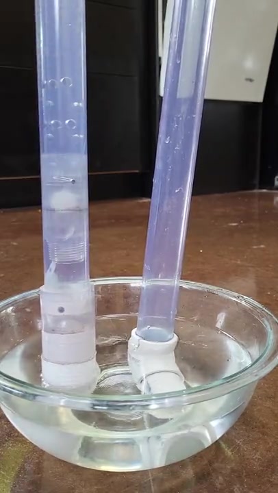
In the pump, the valve allows upward flow with the retaining pin toward the outlet. After the joint cools, we check the ball’s movement, the joined rim, the pin opening, and how water passes forward and is stopped from flowing back. Materials need to be suitable for water contact. These workshop checks do not establish a pressure rating or drinking-water certification for the modified valve.
Step by step
Universal valve, X-rings and perforated pipe
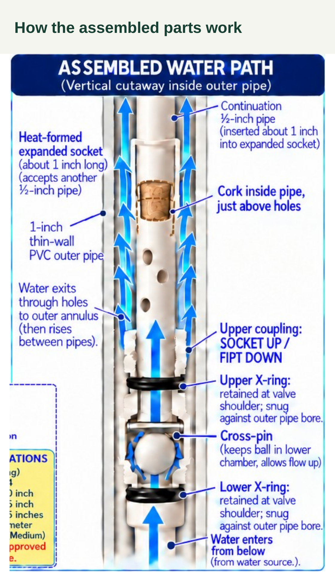
The moving inner valve sends water through side holes and into the space between the two pump pipes.
How the moving inner valve diverts water through side holes into the space between the pipes.
Step 1
Place the X-rings
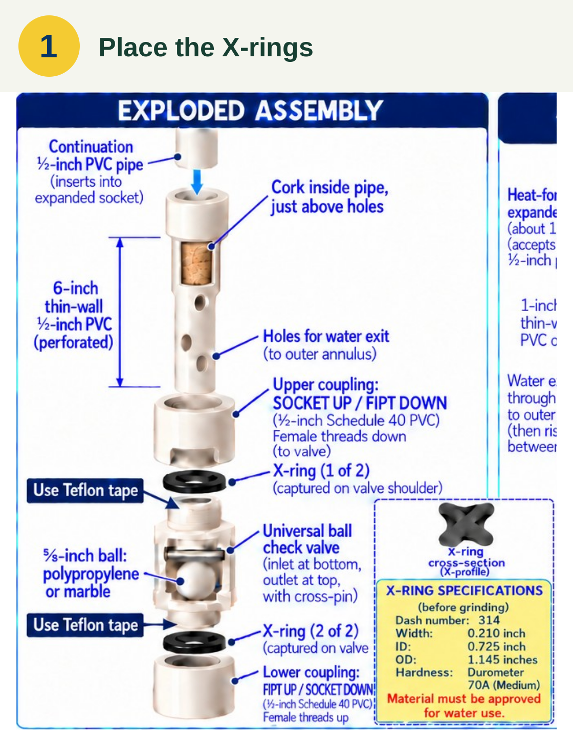
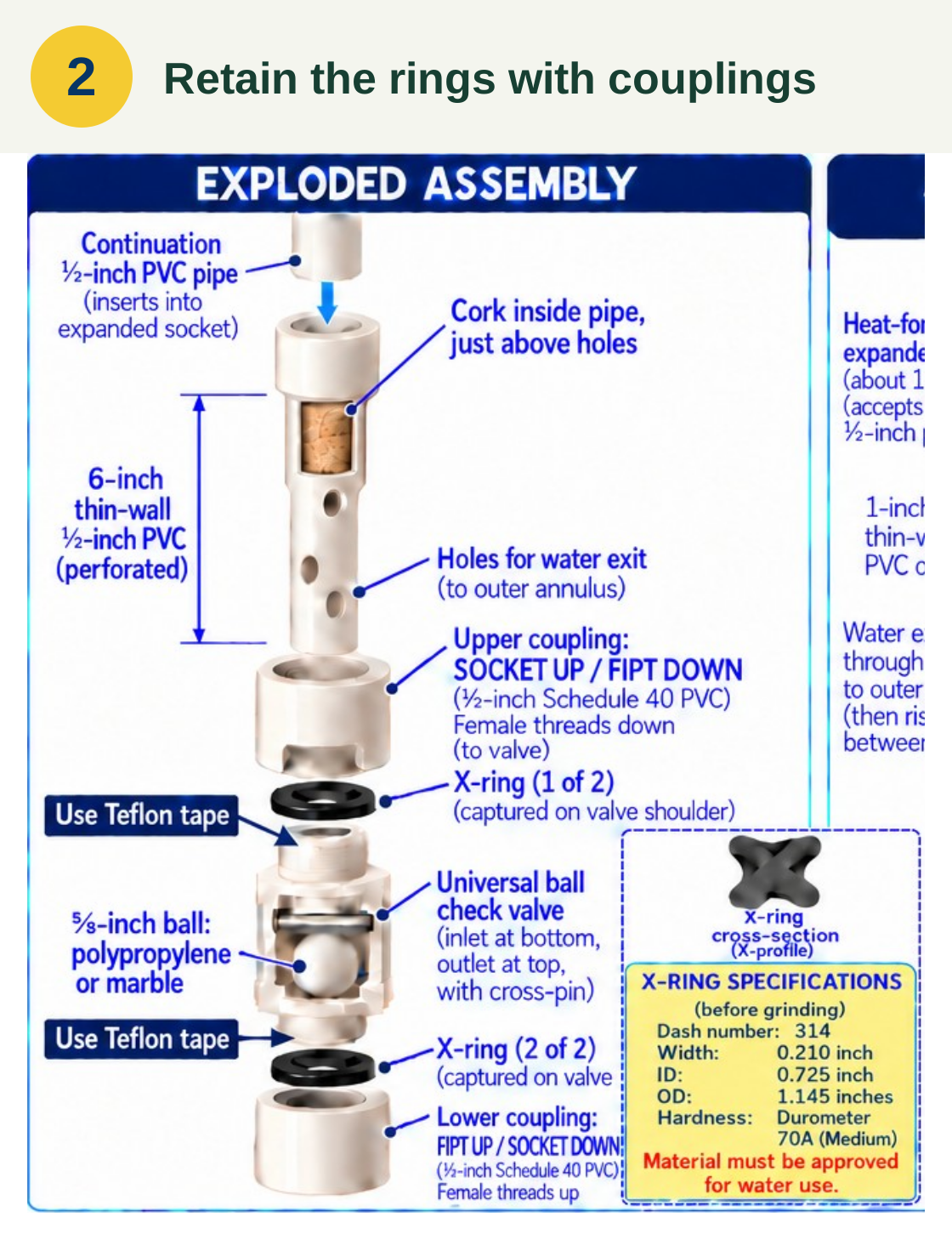
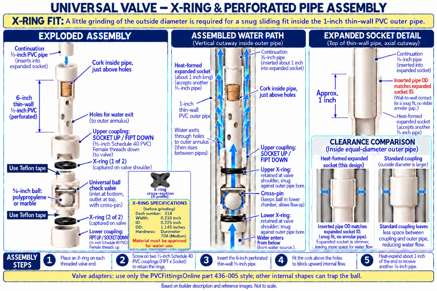
One X-ring sits on each threaded end of the moving valve, against its shoulder. These rings seal against the inside of the 1-inch pipe while the valve slides up and down. PTFE thread tape seals both threaded connections.
Place one X-ring on each threaded valve end, captured at the valve shoulder. Use PTFE thread tape on both threaded connections.
Step 2
Retain the rings with couplings
Two ½-inch Schedule 40 FIPT × Socket couplings hold the X-rings in place. The upper coupling has its socket facing up and its female threads facing the valve; the lower one has its threads up and its socket down. Together, they retain the rings at the valve shoulders.
Screw on two ½-inch Schedule 40 PVC FIPT × Socket couplings. Upper coupling: socket up, female threads down toward the valve. Lower coupling: female threads up, socket down.
Step 3
Insert the perforated pipe
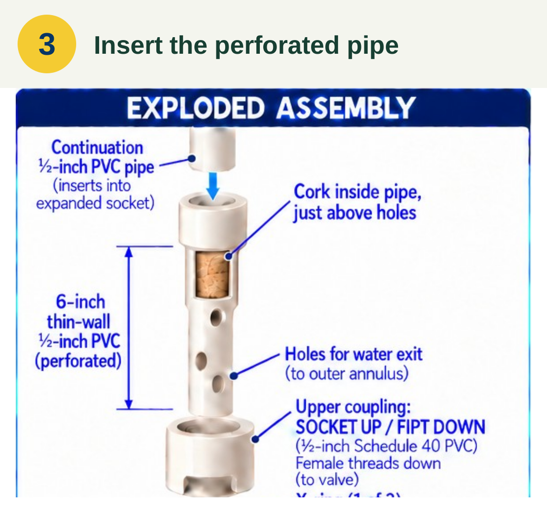
Above the valve is a 6-inch piece of thin-wall ½-inch PVC with holes in its sides. Water comes up through the valve and leaves through these holes. From there, it continues upward between the inner and outer pipes toward the spigot.
Insert a 6-inch piece of thin-wall ½-inch PVC with side holes above the valve. Water passes upward through the check valve, exits through these holes, and continues up the annular space between the ½-inch and 1-inch pipes.
Step 4
Fit the cork above the holes
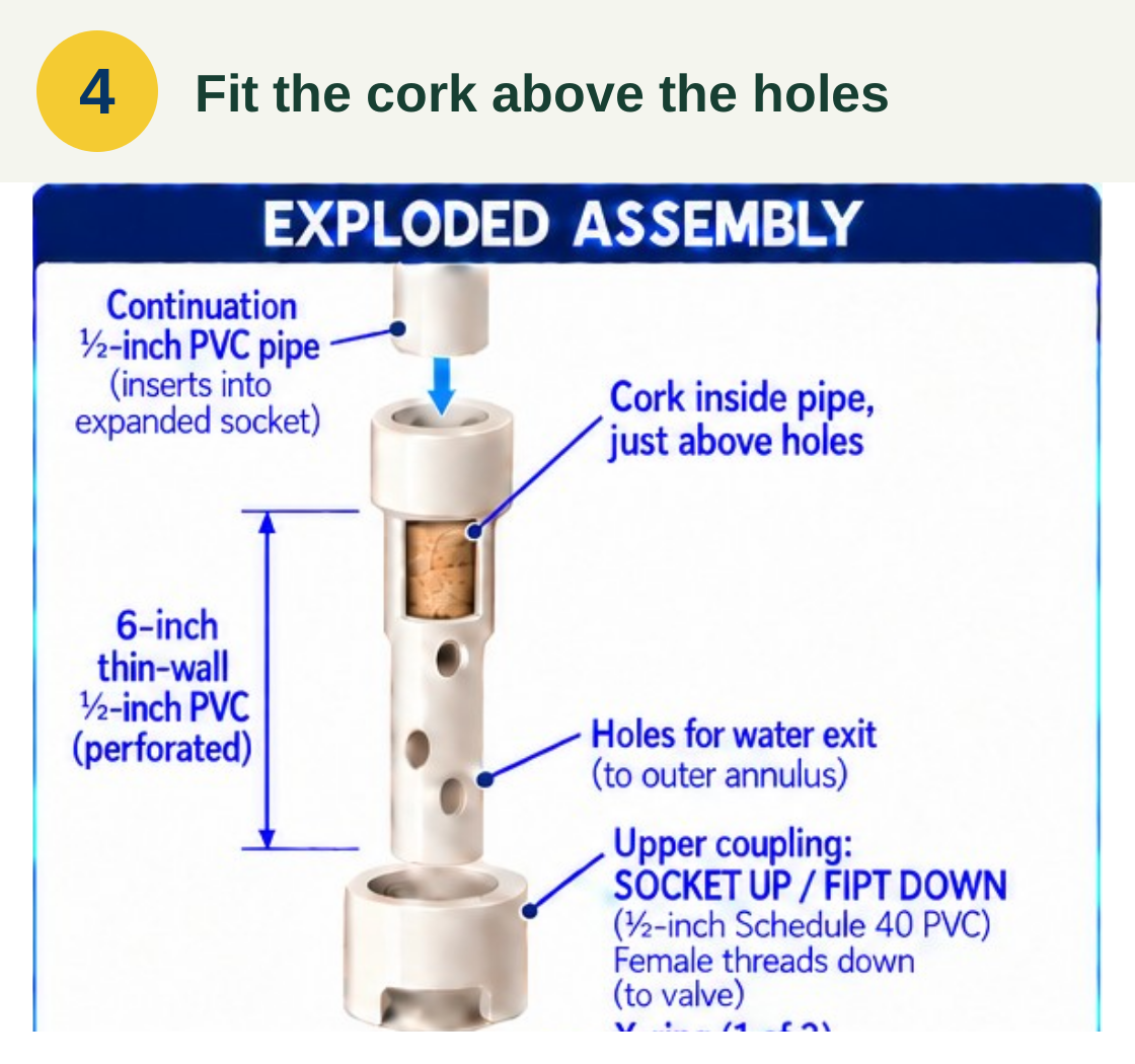
A cork sits inside the ½-inch pipe just above the highest hole. It blocks the path farther up the inside of that pipe, directing the water sideways through the holes instead. The water then rises around the outside of the moving pipe.
Fit a cork inside the ½-inch pipe just above the highest hole. It blocks water from continuing up the inside of the moving pipe.
Step 5
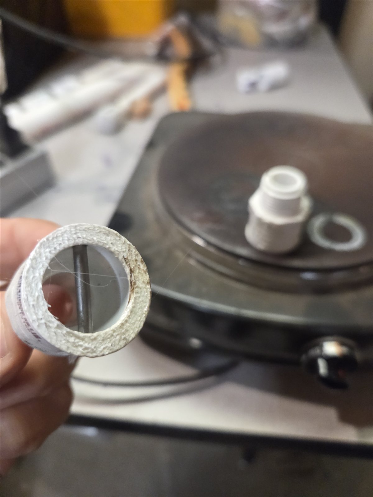
Heat-form a slim socket
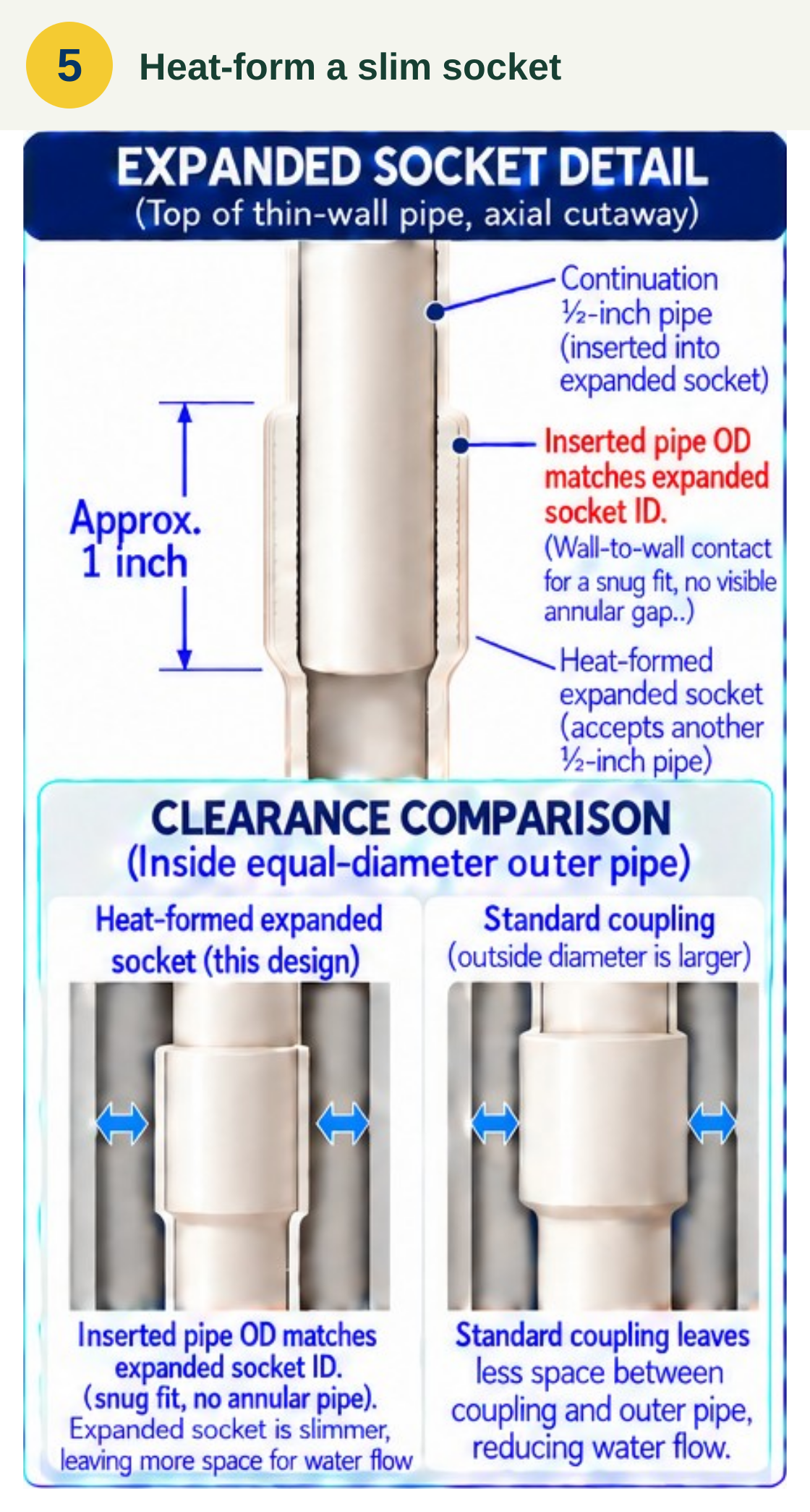
We heat-form about 1 inch of the pipe end into a receiving socket for the next ½-inch pipe. The fit is snug, with the inserted pipe’s outside wall meeting the expanded socket’s inside wall. This joint has less bulk than a standard coupling, leaving more room for water to pass between the pump pipes.
Expand about 1 inch of the pipe end to receive the next ½-inch pipe. The inserted pipe’s outside diameter matches the expanded socket’s inside diameter, with a snug wall-to-wall fit and no visible annular gap. This slimmer joint leaves more space for water than a standard coupling.
Preview the complete print sheet
 See the illustrated steps